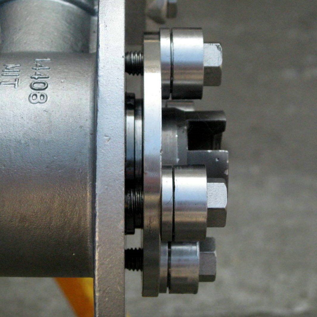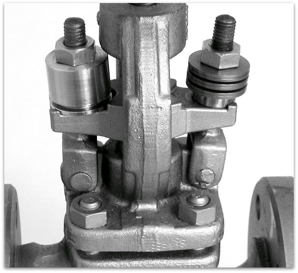
Spring loading systems for valves
Due to their material structure, stuffing box packings show signs of settling. This is due to small air inclusions in the starting material, outgassing of impurities and the fact that the successive rings from the gland to the packing ring in contact with the medium are not compressed uniformly. These settling phenomena can be largely compensated by additional springing.
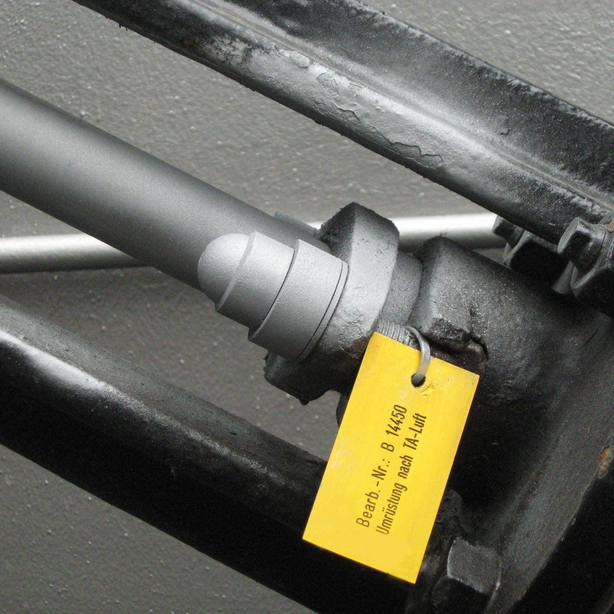
Requirements for a re-equipment
- Equipment according to required specification (TA-Luft, FDA, BAM, ...)
- Service life according to specification and number of shaft movements
- Spring columns designed for packing type
Solutions
- Calculation of optimum / permissible preload forces
- Calculation of the required installation forces at operation
- Adjustment of the sealing pressure for operating under consideration of the installation technology
- Use of additional spring loading systems in case of settling phenomena
Design limits
- Design pressure: up to > 1100 bar
- Design temperature: up to approx. 750°C
- Packing diameter: without limitation
- Packing width: up to approx.30 mm
- Bolt size: up to approx. M36